Shadow Mapping with Directional Light
Workflow
-
Render the scene from light’s perspective, values in z-buffer is the shadow map.
-
Render the scene from camera’s perspective. Check if current fragment is occluded by using shadow map.
-
PCF, set a bias for shadow acne, etc.
Implementation
-
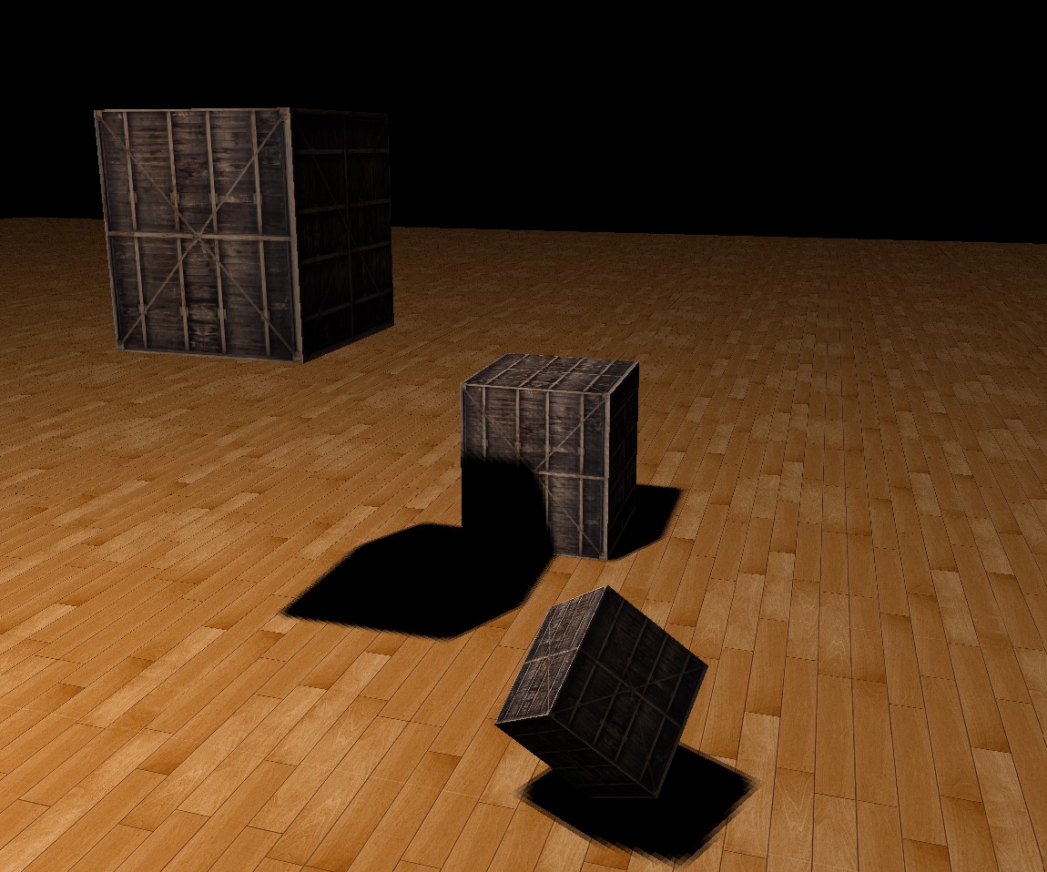
Render the scene from light’s perspective. This demo has 1 and only 1 directional light as light source.
- Since it’s directional light, orthographic projection is used to calculate projection matrix.
- View projection is calculated based on light source’s position and orientation.
-
Model matrix doesn’t change.
Visualized Shadow Map:
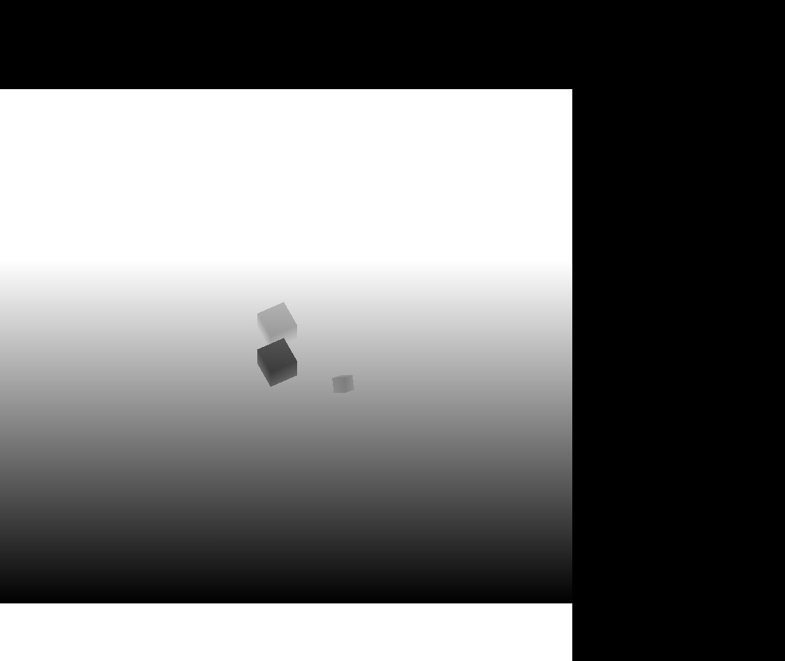
- The darker the region the smaller z value is.
- The size of shadow map depends on the size of depth map, in this case, the size of texture. Left down part of above picture is the shadow map.
- Render the scene from camera’s perspective. Using Shadow Map to calculate shadow.
- In vertex shader, transform vertices from local space to “light source” clip space by applying PVM from part 1 and pass the coordinates to fragment shader.
vs_out.lightSpaceFragPos = lightProjection * lightView * model * vec4(aPos, 1.0f);
- Since OpenGL does perspective division after vertex shader. The “light source” clip space coordinate should perform perspective division manually.
vec3 projCoord = fs_in.lightSpaceFragPos.xyz / fs_in.lightSpaceFragPos.w; /* clip space to NDC */
- Now coordinates are in NDC, in the range of [-1.0, 1.0]. Coordinates in depth buffer is in the range of [0.0, 1.0]. Mapping coords from [-1.0, 1.0] to [0.0, 1.0]
projCoord = projCoord * 0.5f + 0.5f;
- Fianlly, sampling values from shadow map.
float closestDepth = texture(depthMap, projCoord.xy).r;
- Compare values in depth buffer with the fragment’s z value. If fragment’s z value is larger, it means it was occluded which should be in the shadow.
float currentDepth = projCoord.z;
float shadow = currentDepth > closestDepth;
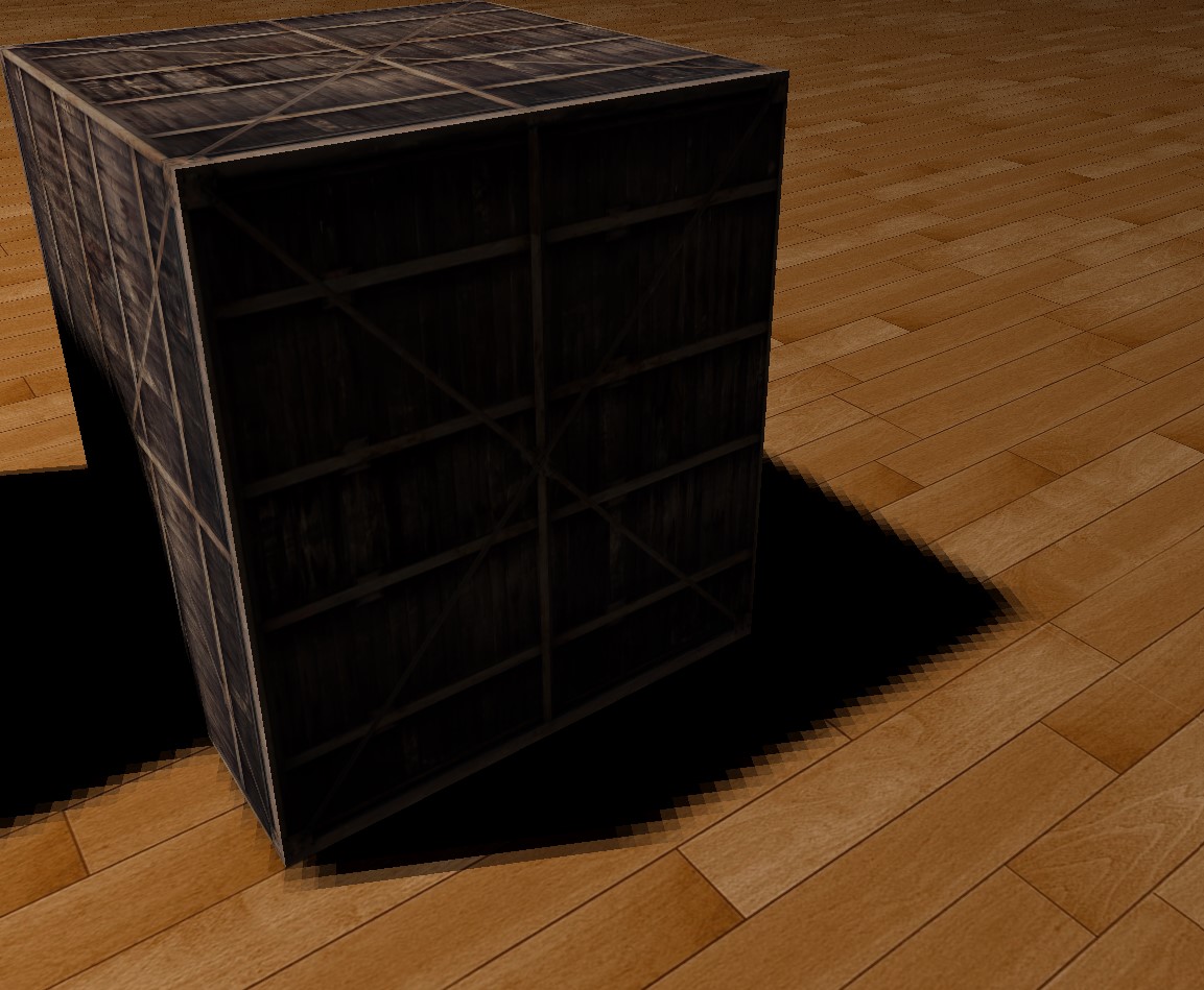
Result:
- In vertex shader, transform vertices from local space to “light source” clip space by applying PVM from part 1 and pass the coordinates to fragment shader.
-
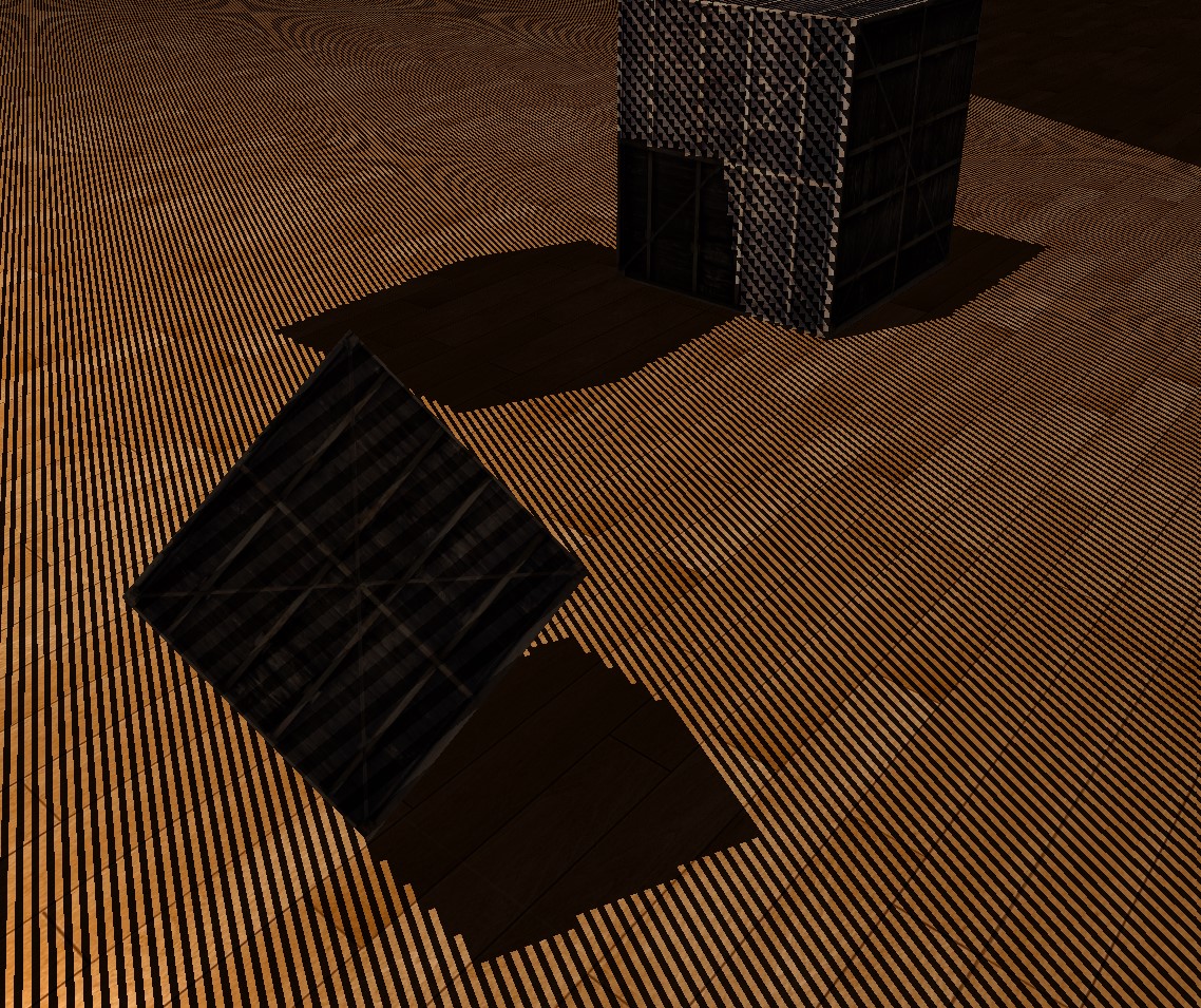
PCF, set a bias for shadow acne, etc.
-
The picture above has black lines, it’s called shadow acne. In short, low resolution of shadow map causes this.
-
One of the solutions is add a bias to fragment’s z value.
After bias applied:
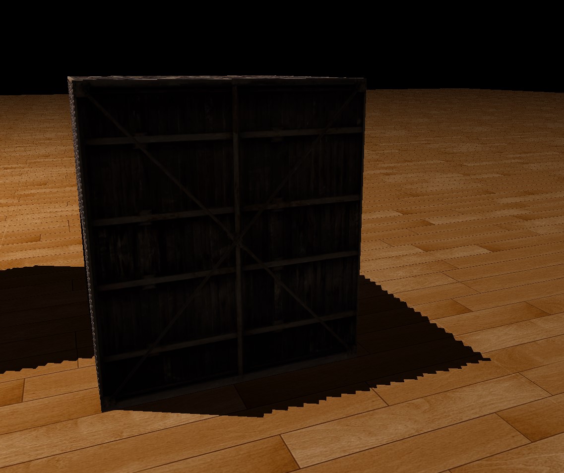
- The picture above also has zig zag edges.
-
Applying percentage-closer filtering(PCF), this demo simply samples surrounding texels and average the result. This produces relative soft edges.
PCF:
-
Resource
https://learnopengl.com/Advanced-Lighting/Shadows/Shadow-Mapping
https://learnopengl.com/Advanced-Lighting/Shadows/Point-Shadows
https://www.youtube.com/watch?v=6Ofj9xppNew